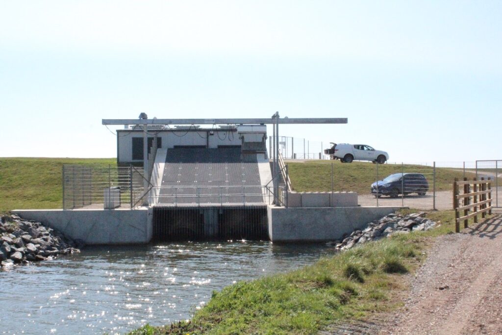
The original pumping station was built in 1951 but by 2022 the site was deemed to be at “end of life” and a new-build pumping station was required to safeguard the surrounding catchment. By 2023 construction was underway on a new site adjacent to the Wash on the Lincolnshire coast.
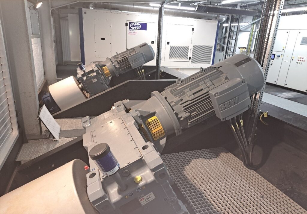
The design and construction of the new pumping station encompassed the employment of 2 x 2000mm diameter Archimedes Screw (Fishflow Innovations) rated at 90kW each. These pumps provide a total capacity of 2,300 litres per second (2.3 cumecs).

The New Pumping Station
The catchment protected by the new pumping station covers 2187.2 hectares the majority of which is arable land also including over 200 residential and commercial properties.
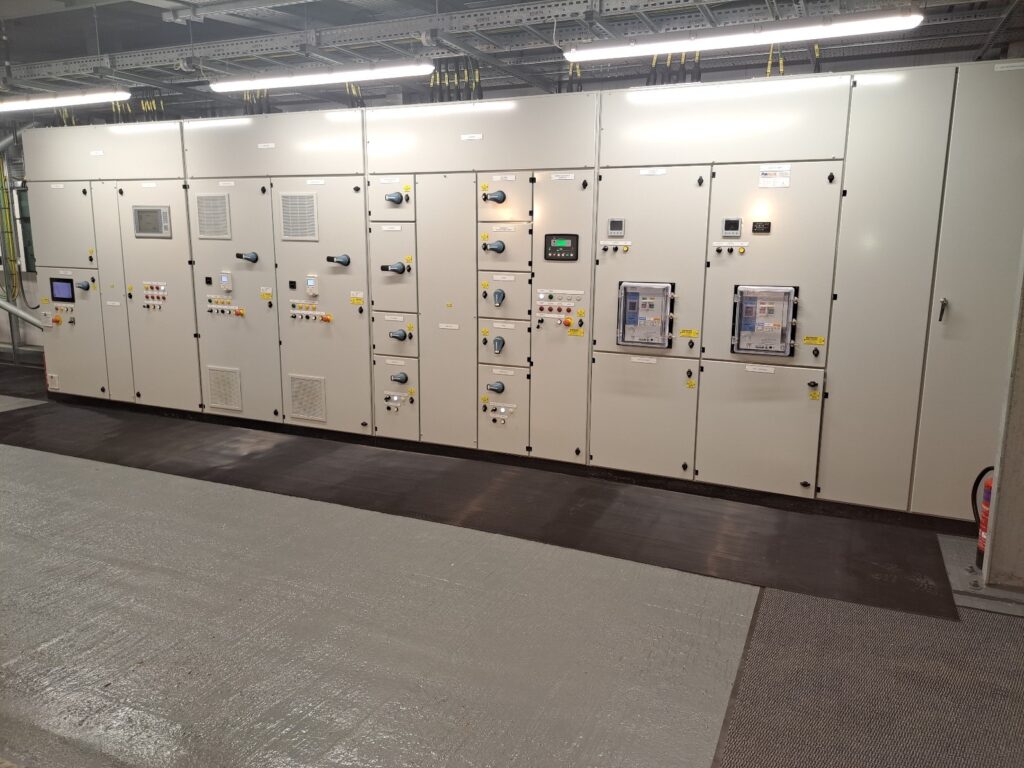
A major Water Equipment and Pump Manufacturer was awarded the overall MIECA contract and they in turn awarded the design and manufacture of a fully automated and intelligent MCC to Paktronic.
Following on from a number of in-depth meetings with the overall design consultants, the pump manufacturers and the Internal Drainage Board (end client), Paktronic put forward the proposed MCC arrangement:
The overall MCC consisted of 5 Sections (straight-line configuration) measuring 7200mm L x 2300mmH x 750mm D.

The New MCC
Section 1
- DNO Cutouts & Metering
Section 2
- Generator Incomer (800amp ACB)
- Mains Incomer (800amp ACB)
- Automatic Changeover to Generator (in the event of mains power outage)
Section 3
- Power Distribution Feeders
- Penstock 1 Actuator Control (1.1Kw Reversing Starter)
- Penstock 2 Actuator Control (1.1Kw Reversing Starter)
Section 4
- Screw Pump 1 Controls (90Kw Low Harmonic VSD & Ethernet)
- Screw Pump 2 Controls (90Kw Low Harmonic VSD & Ethernet)
Section 5
- ICA (PLC & HMI for automatic control of the pumping station)
- Automatic Weedscreen Cleaner Controls
- Telemetry Unit
The MCC control system provides overall automatic control of the pumping station.
Four radar level transducers monitor the water levels at;
- Inlet drain
- Two sumps
- Outfall
Signals from the level transducers are processed by the PLC, providing “levels” information to the HMI.
The system monitors the differential between the inlet drain and the sumps. If the differential increases above a setpoint (indicating a blockage) then a start signal is sent to the Weedscreen controller to commence a cleaning cycle.
On each pump start command the Weedscreen controller will initiate a cleaning cycle.
The PLC system monitors the 2 sump water levels and once a preset water level is reached, the duty pump starts. The pump motor VSD will ramp up to 20Hz and if the drain level keeps rising it will ramp up to a maximum of 35Hz. Once this speed is reached and the drain level is still rising, the assist pump start level setpoint will be reached and then the assist pump will start.
With both duty and assist pumps running the speed of both is reset to 20Hz. Again, increasing the speed up to a maximum of 35Hz until the drain level starts to lower. At which point both VSDs will start to decrease the motor speeds in one Hz increments. As the drain level lowers the assist pump stop level setpoint is reached the assist pump will stop. The station will then be running on the duty pump only until the duty pump stop level is reached.
There is a hardwired backup level control system in place in the event of a failure of the level transducers and/or PLC system. This utilises level conductivity probes. These are located in the two sumps and provide a high-level signal (start pumps), low level (stop pumps) and low, low level (inhibit pumps). The high-level probe is set above the pump start setpoints and if this level is reached then the backup control system takes over the pump control from the PLC system and will run both pumps at 45Hz until the low level is reached. At this point the pumps will stop and revert to PLC control again.

The screw pumps lift water from the inlet drain into the two discharge chambers (one per pump) which are located underneath the floor of the pumping station. The water then flows out under gravity through the open penstocks, through the flap valves into the outfall channel and finally out to sea.
The discharge chamber has level conductivity probes for high level in the event of a high tide or storm surge which may prevent the flap valves from opening during pumping operations. When the high level is reached the pumps will be inhibited.
The outfall level is monitored by a radar level transducer. When the transducer detects a high level on the outfall, the two penstocks will close to prevent salt water from entering the discharge chambers. Penstock “closed” signals are detected by the PLC and pump operation is automatically inhibited. For fail safe operation there are also hardwired interlocks.
At the outfall two flap valves prevent the backflow of salt water into the drains. These are opened under the weight of the water whilst the pumps are in operation.
The fish friendly screw pumps allow the passage of the adult European eels to commence their migration to the Sargasso sea where they will spawn and then die. Additionally, an Eel Pass system assists the passage of the European Eel Elvers on their journey from the Sargasso sea into the inland drains and waterways where they will live out their lives until it is time for them to undertake the migration.
